 Made
in the USA
Made
in the USA
Installation & Startup
Uppacking | Pump Location | Piping Connections | Vacuum Piping | Exhaust Piping | Service LIquid Inlets | Service Liquid Supply Options | Motor and Electrical Information | Wiring & Startup
Unpacking: Inspect the shipping container, pump and motor for external damage. Check the pump for dents, and the motor for damage to the junction box, fan shroud and fan.
To inspect for hidden shipping damage, turn the pump rotor completely around one rotation, counter clock wise. This can be done with a screw driver inserted through the vacuum or exhaust port. The rotor should turn freely without any scraping or noise. If it doesnʼt, there may be hidden damage.
File a claim with the Carrier immediately if external or hidden shipping damage is observed.
Pump Location: Locate in a well ventilated and reasonably clean area near a water supply and drain. Other considerations include: being near the process being served; near an outside wall if the exhaust is to be piped outside; and in an area where temperatures are above freezing.
Piping
Connections:
Vacuum Piping: For
short runs, size the vacuum line to be at least as large as the vacuum
port, 11⁄2 inches diameter. When two or more pumps are piped together in
parallel, size the line to be close to the sum of all the inlets.
Suggested diameters are 2 1/2 inches for 2 pumps, 3 inches for 3 to 5
pumps, and 6 inches for 6 to 8 pumps.
For long runs, the line size will depend on the length of run and number of fittings. These should be sized for minimum pressure drop. Contact the factory for more information on this.
Vacuum piping should drain down toward the pump and enter the vacuum port from above. Low points in the piping where liquid can collect and cause slugging should be avoided. Exhaust piping should be directed down toward a drain. This allows partial draining through the exhaust port when the pump is shut off, and damaging stresses from flooded or dry restarts are avoided.
Use an inlet check valve to prevent water in the pump from being sucked back into the process when the pump is shut off. This also allows the pump to retain sufficient water for self priming which is a necessity in 100% recirculation systems. Also, when two or more pumps are piped in parallel and cycling separately, use one on each pump to prevent those that are operating from drawing air and service liquid from those that are not.
Use a vacuum relief valve in the vacuum line to control vacuum to the desired level, and to prevent the pump from “blocking off” and cavitating.
Lyco pumps feature a higher tolerance for handling liquid and solids because of a strategically located 1/2" drain to which a hand valve can be attached. This valve can be opened to allow the pump to handle more service liquid water and condensate, and to flush out solids, eriodically or continually.
Exhaust Piping: The exhaust from the pump is composed of a high velocity mixture of gas and liquid. It should be freely discharged into the atmosphere to avoid excessive back pressure which can stress pump components and overload the motor. Standard motors will handle a modest amount of back pressure; however, a larger motor may be required where excessive back pressure is unavoidable.
Use a separator/muffler attached to the exhaust port, to avoid back pressure by separating the high velocity mixture of gas and liquid by immediately reducing its velocity. The liquid, gently flows down through a bottom fitting which can be piped directly to a drain while the exhaust gas rises and discharges freely into the atmosphere through a fitting at the top. The exhaust can be piped outside or to any other location, provided that the pipe is sized large enough to avoid back pressure and is not connected directly to a drain.
At the same time a separator/muffler allows more quiet operation, since the high pitched sound from the pump discharge is easily attenuated by changing direction of the exhaust.
For short runs, and if a separator/muffler is not used, size the exhaust line to be as large as the exhaust port, 11⁄2 inches diameter. Make it short and point it down near a drain, but DO NOT CONNECT IT DIRECTLY TO A DRAIN since this will cause back pressure. The discharge will continue to be a high velocity mixture, but if the line is short and the discharge is into the atmosphere, there will be minimum back pressure.
For longer runs, consider larger diameters. For example, a 3 inch elbow attached to the exhaust port and pointed down will also slow the outlet velocity sufficiently to separate the mixture and produce a gentle flow of liquid. This elbow can be connected to a 3 inch line which can be directed to a drain, but again, DO NOT CONNECT IT DIRECTLY TO A DRAIN.
Also, avoid back pressure by not piping the pump exhaust to a location above the pump. This requires the pump to work harder in order to push the exhaust mixture up hill. And, when it is shut off, liquid will run back into the pump and flood it. Flooded restarts significantly stress motors and all pump components because of the hydraulic pressures produced. If this piping arrangement canʼt be avoided, it should be understood that a larger motor may be required, and that flooded restarts can result in higher, long term, maintenance costs.
General rules, for avoiding back pressure include: The pump should be allowed to partially drain through the exhaust port when the pump is shut off. There should always be an air break in the exhaust line before it enters a drain. And, the line should be sloped down toward the drain without low points or traps where liquid can accumulate and cause restriction.
Service Liquid Inlets: The pump includes two service liquid inlets, see “Piping Connections” . These two inlets are used together or independently, depending on the supply option chosen. See the next section titled,“Service Liquid Supply Options”.
The primary inlet is where the main water supply is connected. This is a 1/2" MNPT nipple which is threaded inside to accept a 3/8" pipe plug which can also be used as a fixed orifice by drilling a hole in it. Capacities of these pumps are rated at 2-3 gpm of water at 60˚F. Capacities will vary somewhat with water flow. Lower water flow will generally produce less maximum vacuum, while higher water flow, will generally produce higher maximum vacuum.
| gpm @ 40 psi | gpm @ 40 psi | ||
| 1/16" | .55 | 9/64" | 2.5 |
| 1/32" | 1.20 | 5/32" | 3.75 |
| 7/64" | 1.30 | open | 5-6 |
| 1/8" | 1.90-2.00 |
Flows through orifices at normal 40 psi water line pressure are as follows.
For different line pressures, use a different orifice size or a constant gpm/variable pressure orifice which will provide the rated gpm for any line pressures between 15 and 125 psi.
The recirculation inlet is located in the suction side so the pump will draw its own recirculation service liquid without the need for a separate liquid pump. This inlet can also be used for drawing acid into the pump for periodic descaling. This is a 3/8" MNPT nipple which is threaded inside to accept a 1/4" pipe plug which can also be used as a fixed orifice by drilling a hole in it. For 100% recirculation, a 1/4" hole at 15" Hg vacuum will allow 2 gpm flow. For 50% recirculation, 1 gpm, a 5/32" hole is required at 15" Hg.
General Notes:
- Keep all connecting pipes and fittings clean of metal filings and chips before connecting to avoid having them get into the pump when it starts up.
- In all cases, the piping should be independently supported to AVOID PUTTING EXCESSIVE WEIGHT ON THE FRONT OF THE PUMP. Use flexible connections where appropriate.
In the standard Lyco package, pumps are mounted on top of a stainless steel recirculation tank. This tank includes a stainless steel float valve to control the level of service liquid (usually water), since about 1-2 gallons per hour per pump will be lost by evaporation. Also included are fittings for drain and overflow connections, and a maintenance access panel.
A manually operated, auxiliary service liquid line is included for conveniently filling the tank and priming the pump. Donʼt start the pump until this had been done. Water level can be observed through the clear, recirculation hose. The auxiliary line can also be used for cooling when high temperatures may interfere with performance needs.
Service liquid water temperatures will rise during recirculation and balance out at some level. This level will depend on the pump size, room temperature and incoming heat from the process. As the temperature rises, performance drops, particularly at higher vacuum levels. For example, at 120° F water, capacities in the 10-20 in-hg vacuum range can be 10-20% lower and in the 10-20 in-hg vacuum range, 20-40% lower than catalogue ratings which are based on 60° F water temperature.
If this is a problem, consideration should be given to over sizing the pump or using a heat exchanger.
Note: ALWAYS USE A CHECK VALVE IN THE VACUUM LINE WHEN USING A RECIRCULATING SYSTEM. This allows the pump to retain sufficient water for self priming when it is shut off, and allows it toproduce sufficient vacuum to draw service liquid up from the tank when it is restarted.
Motor and
Electrical Information: MOTORS FOR CLOSE-COUPLED PUMP MODELS
101 & 102: Standard motors are close-coupled, energy efficient, totally
enclosed, three phase, and have the following features:
• Oversized, stainless steel shafts.
• Oversized, permanently lubricated bearings.
• Comply with EPACT & NRCan efficiency standards.
• NEMA Design B performance, Class F insulation.
• 1.25 service factor.
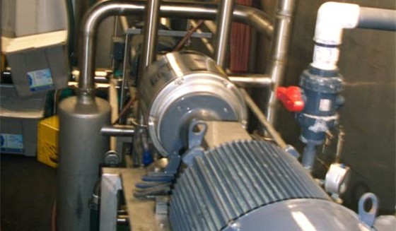
MOTORS FOR PEDESTAL MOUNTED PUMP MODELS 501 & 502:
Standard motors are general purpose, premium efficient, totally enclosed, three phase, and they have the same electrical features as the close-coupled motors shown in the table above.
Non-standard motor selections for pump Models 501&502, are unlimited, since they are separate and connected to the pump with a coupling. This pump model is used for selections such as explosive-proof and severe duty motors, and for oversized motors.
Note that if a non-standard motor with a 1.0 service factor is selected, the next size larger motor should be used.
When field mounting motors for pump Models 501&502, the motor shaft must be properly aligned with the pump shaft, or premature coupling or bearing failure can occur. No more than 1 degree angular or 1/64 inch parallel offset should be tolerated:
Wiring and Startup:
- Use the wiring diagram inside the motor junction box for instructions. Note that closecoupled, Models 101&102, 3 and 5 hp motors, have “Wye” wiring connections while the 7.5 and 10 hp motors, have “Delta” connections.
- Fill the pump with service liquid (usually water) up to the bottom of the inlet and exhaust ports. Do not start the pump without water. With a recirculating system, also fill the tank.
- Check the pump rotation by jogging the motor on. Direction of rotation should be counter clockwise when facing the front of the pump.
- There are three options for wiring the same three phase motor, and each one can have a different percent of current unbalance between legs. It is desirable to find the option with the least percent of unbalance by wiring the motor all three ways during startup. To prevent changing the motor rotation when this is being done, the motor leads should be rolled across the starter terminals by always moving them in the same direction.
Use the following steps to calculate current unbalance for each of the three wiring options:
- Get three amp reading, one for each leg, add them together and divide by 3 to get the “amp average”.
- Of the three readings, determine which one has the “greatest amp difference” between it and the average. Then, divide this difference by the average to get the percent of unbalance: % Unbalance = 100 x “Greatest Amp Difference” ÷ “Amp Average”
Percent of unbalance should not exceed 5%, to avoid shortened motor life. If there is more than a 5% unbalance in all three wiring options, the problem is probably in the power supply.
Uppacking | Pump Location | Piping Connections | Vacuum Piping | Exhaust Piping | Service LIquid Inlets | Service Liquid Supply Options | Motor and Electrical Information | Wiring & Startup