Maintenance
Trouble Shooting | Pump Disassembly and Shaft Seal Removal | Pump Reassembly and Shaft Seal Installation | Clearance Adjustment Prodecures | Factory Rebuilding
Trouble Shooting:
A. Decrease or loss of performance-check the following:
- All fittings, connections, lines and tanks for air leaks into to the system.
- Service liquid flow into the pump. It should be 2-3 gpm of water. If low, check for obstructions in the piping, valves, strainers and orifices. Also check for low water pressure in the main water supply. For recirculation tanks, see item E.
- Service liquid temperature, since performance is reduced as temperature increases. Catalogued performance is based on 60° F water. For information on temperature effect, contact factory.
- Fluctuating pressures in the water supply if performance is fluctuating. Resolve with a constant gpm/variable pressure orifice in the service liquid line.
- Scale build up. Resolve with descaling acid.
- Too much clearance between the rotor (27) and porting turbine cover (36). Factory setting is .005-.010 inches with the six through bolts (37) “cross tightened” equally to 6 ft-lbs (72 in-lbs). Too much clearance can be caused by:
- Loose through bolts. This can be corrected by “cross tightening” all six through bolts equally to 6 ft-lbs.
- Adjusting setscrews (31) that have been previously disturbed. See “Disassembly and Shaft Removal” paragraph “D".
- Clearance lost by long term wear. This clearance can be regained to some extent by
tightening through bolts to more than 6 ft-lbs. Note each 1/10 turn equals .005 inches. Avoid seriously over tightening since this can distort the porting turbine cover (36) and also cause rubbing. - Note, use Loctite #242 on all threaded connections, and for more sophisticated adjustment procedures, see“Clearance Adjustment Procedures”.
B. Leaks in the pump:
- Check torque on through bolts (37), and if they have loosened up, “cross tighten” them to 6ftlbs (72in-lbs) with a torque wrench. Use Loctite #242 on all threaded connections
- If leak is in the back of the motor turbine cover (21) and between it and the motor or the bearing house, a new shaft seal is needed. A leaking shaft seal should be replaced as soon as possible, see “Seals”.
- If leak is in front of the motor turbine cover (21), a new o-ring (23) may be required, but if the o-ring groove is cracked, a new motor turbine plastic (22) is required. For a temporary fix, fill the crack with silicone sealant.
- If leak is in the back of the porting turbine cover (36), a new o-ring (23) may be required, but if the o-ring groove is cracked, fill it with silicone sealant as a temporary fix. Eventually, the porting turbine cover should be factory repaired or replaced. Cracked o-ring grooves are usually caused by excessive weight on the front of the pump or by using a screw driver to pry it apart when servicing. Always use a rubber hammer to tap it apart.
C. Excessive noise and vibration—check for the following:
- Cavitation. It sounds like nuts, bolts and screws violently rattling around inside the pump, and it is destructive. It occurs near the “blocked-off” vacuum level, and is aggravated by excessive liquid flow into the pump. Solve by bleeding air into the Maintenance (refer to parts list Page 20) 12 vacuum line, and reducing water flow to 2-3 gpm, if possible. If not, excess water can be relieved through the pump drain to which a hand valve can be attached to control flow.
- Liquid slugging through vacuum inlet. It sounds like cavitation and is equally destructive.
- Excessive amounts of liquid flow, over 2-3 gpm, entering pump.
- Scale build up.
- Motor vibration (Models 101&102), bearing vibration (Models 501&502).
- Coupling misalignment (Models 501&502).
- Backward rotor rotation.
- Rotor loose on shaft.
- If noise is only the high pitched sound from the pump exhaust, it can be easily attenuated by changing direction of the exhaust.
D. Motor trouble:
- High Running Amps -- check for the following:
• Restriction of exhaust line which causes back pressure which causes motor to work harder.
• Excessive amounts of liquid flow, over 2-3 gpm, entering pump.
• Cavitation
• Liquid slugging through vacuum inlet.
• Rubbing between rotor (27) and porting plate in the porting turbine cover (36).
• Low or high voltage.
• Loose wire connections at motor or starter.
• Excessively high motor ambient.
• Current imbalance between legs on three phase motors. - Noise and vibration—check for the following:
• Loose wiring connections on one leg, single phasing.
• Bad bearings. - If motor problems persists, check with authorized motor repair shop.
E. Trouble shooting with a recirculation tank:
- Follow procedures in steps A through D, above, plus check the following:
- If pump will not produce vacuum at startup, check if recirculation water is being drawn up from the tank. If not, prime pump and restart.
- Be sure inlet check valve is functioning. It must keep liquid in the pump when it is shut
off, or the pump will not be self priming. - Check the flow control orifice in the recirculation line. If plugged, pump will receive little or no water. If missing, pump will receive too much water.
- Check water temperature in the tank. High temperatures will not harm the pump, but they will affect performance. In extreme cases, there may be insufficient vacuum to draw recirculated water up from the tank. Reduce temperature by letting in cool water through the auxiliary service liquid line.
- If the system vacuum level falls below 5-7 in-Hg at anytime during the process cycle, there may be insufficient vacuum to draw water up from the tank, and the pump can run dry. A higher vacuum can be induced into pump by partially restricting the inlet. This can be done with a hand valve installed in the line ahead of the pump.
Pump Disassembly and Shaft Seal Removal (refer to parts page):
A. Disconnect power source and drain the pump (34).
B. Remove stainless steel shroud (35) and six through bolts (37).
C. Remove porting turbine cover (36) and cylinder body (33). USE A RUBBER HAMMER TO TAP THEM APART rather than using a screw driver to pry them apart since this can crack the o-ring grooves and cause a leak.
D. Rotor removal (Carefully follow these steps):
- Remove rotor setscrews (28) between the vanes on rotor and located 90˚ apart;
- Remove rotor retaining bolt (32) in end of rotor (27), but DONʼT TOUCH THE TWO ADJUSTING SETSCREWS (31) which are located beside the retainer bolt. This is VERY IMPORTANT for retaining the proper clearance (.005-.010 in.) between the rotor face and the porting turbine cover (36) when the pump is reassembled. If these are disturbed, clearance will need to be reset. Note that the clearance will always need to be reset if the rotor (27), shaft (105) or close-coupled motor (40) is replaced. See “Clearance Adjustment Procedures”, or contact the factory for other suggestions.
- Remove rotor (27) from shaft, being careful to slide rotor over key (29);
- If rotor (27) will not come off freely, turn a 5/8-11 bolt into the rotor, center hole which is threaded, and push off motor shaft.
E. Seal removal: Remove key (29), seal spring (24), and slide seal (24) off shaft.
F. Remove motor turbine plastic (22) by pulling it directly towards you. If it has a cracked o-ring groove or is worn, it must be replaced.
G. The stationary seat portion of seal (24) can now be pressed out of motor turbine plastic (22).
H. Remove the four motor turbine bolts (39), and remove motor turbine cover (21) from the motor or bearing housing if necessary to service these components.
Pump Assembly and Shaft Seal Installation:
A. Place motor turbine cover (21) on motor or bearing housing and bolt in position with the four motor turbine bolts (39). The two machined head bolts are used in the bottom holes. Use Loctite #242 on all threads.
B. Press stationary seat portion of seal (24) into motor turbine plastic (22) until it bottoms into bore. Motor turbine plastic must be replaced if it is cracked or worn. Some servicemen automatically replace this with the seal. Use P-80 THIX (International Products Corp.) glycerin, or a light machine oil (except donʼt use oil with EPDM elastomers) on elastomer cup and shaft side of bellows for easier installation. Donʼt touch sealing surfaces with fingers.
C. Place motor turbine plastic (22) in bored hole in motor turbine cover (21) and align locating lug. Take care when installing to avoid damage to stationary seat portion of seal (24).
D. Replace Shaft Seal: Slowly slide seal (24) on to shaft (use P-80 glycerin or light machine oil, except donʼt use oil with EPDM elastomers) until it touches stationary seat portion of seal. Donʼt touch sealing surface with fingers. Replace spring (24) and key (29).
E. Replace rotor: Push rotor (27) on shaft until adjusting setscrews (31) contact end of shaft. IF THEY HAVENʼT BEEN TOUCHED AS PREVIOUSLY INSTRUCTED THEY WILL PROVIDE PROPER CLEARANCE between the rotor (27) and porting turbine cover (36);
- Replace retainer bolt (32) and rotor setscrews (28). Recommended seating torque for retainer bolt (1/2-13 x 1/2) is 62.5 foot pounds. For rotor setscrews (3/8-16 x 5/8) it is 19.2 foot pounds.
F. Replace o-rings (23) (new o-rings are recommended always), cylinder body (33), porting turbine cover (36), through bolts (37) and stainless steel shroud (35). NOTE: Be sure o-rings and all sealing surfaces are clean.
G. Then, tap lightly around the outside of the porting turbine cover (36) with a rubber hammer to seal it after assembly. “Cross Tighten” the six through bolts (37) equally to 6 foot pounds (72 inch pounds), with a torque wrench. This should provide the same clearance as set at the factory provided the shaft has not shifted as a result of a change in a bearing lock ring location.
H. Notes:
- Use Loctite #242 on all threaded connections.
- Avoid “over tightening” the through bolts (37) since this can distort the porting turbine cover (36) and also cause rubbing.
- If clearance adjustment is required, see “Clearance Adjustment Procedures” below.
Clearance Adjustment procedures (refer to parts page):
Lyco Wausau, liquid ring vacuum pumps are among the easiest to field service if procedures in the section “Pump Disassembly and Shaft Removal”, are carefully followed, The main point is “DONʼT TOUCH THE TWO ADJUSTING SET SCREWS”. This is because they provide a locating point for clearance between the rotor (27) and porting turbine cover (36), and if they are disturbed, the clearance must be reset. Note that clearance must always be reset if the rotor, shaft (105) or close-coupled pump motor (40) are changed. Clearance of .005-.010 inches is basic to performance. If it is too wide, the pump will underperform. If it is too close, rubbing can occur and cause overheating and motor problems. The objective of the following STEPS, is to show how this can be done with reasonable precision. If optimum performance is unnecessary, and if the following repair tools are unavailable, contact the factory for instructions on abbreviated procedures.
Repair tools needed (see to “Parts List” page 23):
- Dial indicator accurate to .001-.050 inch total travel
- Depth micrometer accurate to .001 inch
- Post for dial indicator
- Torque wrench, adjustable up to 10 ft-lbs.
- Torque wrench, adjustable 10-80 ft-lbs., 3/8” drive and with long length 3/16” hex bit (for tightening rotor set screws (28)
STEP 1

A. Partially assemble the pump with motor turbine cover (21), motor turbine plastic (22) and shaft seal assembly (24). See “Pump Assembly and Shaft Seal Installation” (page 13).
B. Before installing the rotor (27), remove the rotor retainer bolt (32), rotor set screws (28) and adjusting setscrews (31).
C. Install shaft key w/pin (29) and rotor (27) on the shaft. Install the rotor retainer bolt (32), and screw it in until the rear of the rotor is approximately 1/8 inch from the upper face of the motor turbine plastic (22). Use Loctite #242 on the bolt threads.
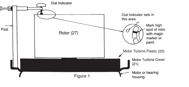
D. Place a dial indicator on the smooth part of the rotor face, rotate it 360 degrees to find the “high point”. Mark this point as instructed in figure 1.
STEP 2

A. Lay porting turbine cover (36) on face of rotor (27).
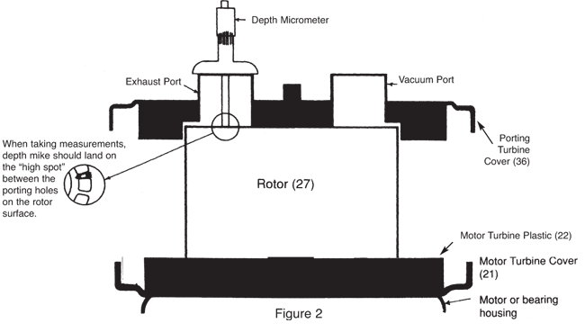
B. From the top of each port, take a depth micrometer measurement to the “high spot” determined in Step 1. Mark the locations from where these measurement were taken on the top of each port, since similar readings will be needed in STEPS 3 and 5. See figure 2.
Record the readings. We suggest they be written on the porting turbine cover (36) along side the port where each reading was taken. Use a pencil for easy erasing later.
| EXAMPLE: | Exhaust Port | Vacuum Port |
| STEP 2 | 1.100 Inches | 1.050 Inches |
STEP 3

A. Assemble the remainder of the pump with the exception of the adjusting setscrews (31) and rotor setscrews (28) which will be installed later in STEP 4. Follow the instructions as described below:
B. Install cylinder body (33) with the drain connection positioned at the bottom-rear of the pump. Line up the six through bolt loops with corresponding six holes in the motor turbine cover (21), and use a rubber hammer to gently tap it down evenly over the motor turbine plastic (22) until it touches the o-ring all around.
C. Place the porting turbine cover (36) into the cylinder body (33) with its six through bolt holes lined up with corresponding loops on the cylinder body, and with the service liquid inlet lined up with the rotor retainer bolt (32). Use a rubber hammer to gently tap it down evenly all around into the cylinder body.
D. Insert the six through bolts (37) with the “castle head” nut ends facing the front. Use Loctite #242 on all threads.
E. Gradually “cross tighten” all of the through bolts (37) until the porting turbine cover (36) begins rubbing on the rotor (27). Determine this by periodically turning the rotor with a screw driver inserted through one of the ports.
F. Lower the rotor (27) on the shaft until it turns freely by turning down the rotor retainer bolt (32) with a 3/8 inch Allen wrench inserted through the 1/2 inch, service liquid primary inlet in the center of the porting cover (36), see page 5. Turn the retainer bolt until the rotor breaks free and turns when the retainer bolt is turned. Note that 1/10 turn will lower the rotor .008 inches.
G. Continue this procedure until the six through bolts (37) are all tightened to six foot pounds (72 in-lbs.) with a torque wrench, and the rotor (27) turns freely when it is turned completely around (360 degrees).
H. Tap lightly on the porting turbine cover (36) all around with a rubber hammer to be sure it is evenly set in the cylinder body (33). Recheck the torque on the through bolts (37), and tighten them if necessary.
I. Make a final check for rubbing by turning the rotor (27) completely around (360 degrees). If it is still rubbing, turn the rotor retainer bold (32) down again until the rotor breaks free and turns when the bolt is turned. At this point the clearance should be about .005 inches.
| Example: | Exhaust Port | Vacuum Port |
| STEP 3 | 1.106 inches | 1.054 inches |
| STEP 2 | 1.100 | 1.050 |
| Clearance | .006 | .004 |
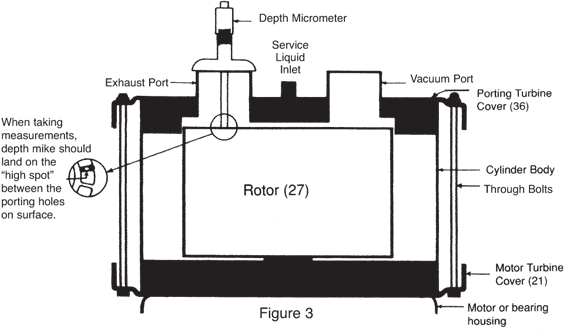
J. Determine clearance by taking two more depth micrometer measurements to the “high point”, one through each port, see Figure 3. Take these from the same locations marked on top of the ports in STEP 2. Record these readings with those from STEP 2, and calculate the differences which are the clearances. Note that clearances at each port are usually different due to tolerance variations in the pump.
The objective in STEP 3, is to have a clearance within the range of .005-.010 inches at the port where the “high point” is closest. A clearance on the low side of the range, as in this example, is desirable; however, if it is above the range, it can be lowered in STEP 4.
STEP 4

A. Partially disassemble the pump, including the through bolts (37), porting turbine cover (36) and cylinder body (33).
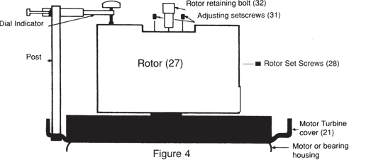
B. Set up the dial indicator again as shown in STEP 1, and set the dial to zero at the “high spot” so that any change in clearance can be measured. Be sure to have adequate travel on the indicator to accommodate adjustments that may be required.
C. Install the two adjusting setscrews (31) on each side of the rotor retainer bolt (32) and tighten them until they are snug against the end of the shaft. Use Loctite #242 on the threads.
D. If the clearance in STEP 3 is on the low side of the .005-.010 range, as in the example, tighten the rotor retainer bolt (32) to 62.5 foot pounds with a torque wrench, and observe the dial indicator reading.
E. If the clearance at any time is more than .010 inch, raise the rotor (27) by slightly backing out the rotor retainer bolt (32) and turning in the adjusting set screws (31). Note that 1/10 turn of the adjusting setscrews is .005 inches for &5hp pump models and .006 for the 7.5&10hp models. Observe the clearance changes on the dial indicator, and when the desired clearance is reached, tighten the rotor retainer bolt (32) to 62.5 foot pounds, using a torque wrench. Then install the rotor setscrews (28) and tighten to 19.2 foot pounds after using Loctite #242 on the threads.
STEP 5
A. Reassemble the pump. Be sure to “cross torque” the through bolts (37) to 6 foot pound (72 pound inches).
B. Turn the rotor (27) completely around (360 degrees) to be sure it isnʼt rubbing.
C. Recheck the clearance using the depth micrometer as in STEP 3. At this point, clearance should be within an acceptable range; however, if it isnʼt or if there is rubbing, STEP 4 should be repeated.
Factory Rebuilding:
Lyco Wausau offers a special, factory, rebuilding program for Lyco owners. This work is done on an expedited basis, so turn around is fast. Some who have “standby” pumps prefer to send all of their Lyco pumps in for maintenance, while others use this service only for major repairs.
Having a standby pump can be advantageous for minimum downtime whether pumps are repaired in your shop or returned to the factory. Lyco owners can contact Lyco for special pricing on “standby” pumps.
Factory pricing for pump maintenance depends on what is required, but even with major repairs, it seldom reaches more than one half the price of a new pump. Rebuilt pumps carry a new pump warranty on all Lyco manufactured parts which are repaired or replaced. The procedure for using this service is as follows:
- Include note on your Purchase order: “Submit quote for approval before proceeding.”
- Fax copy of Purchase order to Lyco Wausau office, and include a copy with the pump being sent.
Trouble Shooting | Pump Disassembly and Shaft Seal Removal | Pump Reassembly and Shaft Seal Installation | Clearance Adjustment Prodecures | Factory Rebuilding

